Product Description
Product Description
Model TP is the third generation single-stage circulation water pump designed for a maximum of 120ºC water and industrial fluids. Compared with the previous generation, the efficiency of the series is increased by 5% on average and TP has been the national energy-saving product certificated. The series has horizontal and vertical structures to meet different installation requirements. To achieve world-class quality, the pump body, and impeller are mechanically molded with coated sand, machined with a four-axis CNC machining center, and finished with electrophoresis. The big pump offers a push-pull base for easy maintenance besides the standard base
Application
Product Advantage
Product Structural Drawing
Hydraulic Coverage
Product Parameters
| Type | Capacity | Head | Speed | Eff. | Shaft Power |
Motor Power | (NPSH)r | Weight | |
| Q | H | n | η | Pa | PM | (m) | (kg) | ||
| (m3/h) | (L/s) | (m) | (r/min) | (%) | (kW) | (kW) | |||
| 125TPW26-22/2 | 154 | 42.8 | 29.9 | 2960 | 70 | 18.45 | 22 | 10.2 | 262 |
| 187 | 51.9 | 28.3 | 75 | 19.49 | 10.5 | ||||
| 220 | 61.1 | 26 | 76 | 20.51 | 10.9 | ||||
| 242 | 67.2 | 23.6 | 75 | 20.75 | 11.2 | ||||
| 264 | 73.3 | 21.6 | 73 | 21.29 | 11.5 | ||||
| 125TPW33-30/2 | 161 | 44.7 | 37.1 | 70 | 23.25 | 30 | 10 | 314 | |
| 196 | 54.4 | 35.8 | 75 | 25.49 | 10.3 | ||||
| 230 | 63.9 | 33 | 77 | 26.86 | 11 | ||||
| 253 | 70.3 | 30.3 | 76 | 27.49 | 11.5 | ||||
| 276 | 76.7 | 27.3 | 71 | 28.92 | 12 | ||||
| 125TPW40-37/2 | 168 | 46.7 | 44 | 70 | 28.78 | 37 | 10.7 | 337 | |
| 204 | 56.7 | 43 | 75.7 | 31.58 | 11.1 | ||||
| 240 | 66.7 | 40 | 78 | 33.54 | 11.5 | ||||
| 264 | 73.3 | 37 | 77 | 34.57 | 12 | ||||
| 288 | 80 | 34 | 72 | 37.06 | 12.5 | ||||
| 125TPW46-45/2 | 175 | 48.6 | 53.1 | 2960 | 70 | 36.17 | 45 | 10 | 440 |
| 213 | 59 | 49.7 | 73 | 39.42 | 11 | ||||
| 250 | 69.4 | 46 | 76 | 41.23 | 12 | ||||
| 275 | 76.4 | 42.9 | 74 | 43.44 | 13 | ||||
| 300 | 83.3 | 38.9 | 71 | 44.79 | 15 | ||||
| 125TPW53-55/2 | 189 | 52.5 | 62 | 2960 | 71 | 44.97 | 55 | 5.6 | 572 |
| 230 | 63.9 | 59 | 73 | 50.66 | 7 | ||||
| 270 | 75 | 53 | 75 | 51.99 | 9 | ||||
| 297 | 82.5 | 50 | 74 | 54.68 | 9.9 | ||||
| 324 | 90 | 45 | 72 | 55.18 | 12 | ||||
| 125TPW60-75/2 | 210 | 58.3 | 65.9 | 73 | 51.66 | 75 | 6 | 652 | |
| 255 | 70.8 | 64 | 75 | 59.30 | 8 | ||||
| 300 | 83.3 | 60 | 76 | 64.54 | 10 | ||||
| 330 | 91.7 | 56.8 | 74 | 69.02 | 12.7 | ||||
| 360 | 100 | 52.4 | 71 | 72.40 | 15.5 | ||||
| 125TPW70-90/2 | 231 | 64.2 | 76.9 | 75 | 64.54 | 90 | 7 | 780 | |
| 281 | 77.9 | 74.3 | 76 | 74.73 | 9 | ||||
| 330 | 91.7 | 70 | 77 | 81.75 | 12 | ||||
| 363 | 100.8 | 63.7 | 76 | 82.91 | 15 | ||||
| 396 | 110 | 60 | 74 | 87.50 | 18 | ||||
| 125TPW77-110/2 | 252 | 70 | 85.6 | 75 | 78.38 | 11 | 8 | 990 | |
| 306 | 85 | 82.4 | 77 | 89.23 | 11 | ||||
| 360 | 100 | 77 | 78 | 96.84 | 14 | ||||
| 396 | 110 | 71.8 | 76 | 101.95 | 17.5 | ||||
| 432 | 120 | 66.3 | 73 | 106.92 | 21 | ||||
Detailed Photos
Product Attributes
| Attribute | Attributes | Value | Optionl |
| Installation | Inlet diameter (mm) | DN150 | / |
| Outlet diameter (mm) | DN125 | / | |
| Direction of rotation | Clockwise from the motor to the pump | / | |
| Entrance orientation | level in | / | |
| Exit orientation | level out | / | |
| Base form | / | ||
| Motor | Motor model | ||
| Number of motor phases | 3 | / | |
| Rated voltage (V) | 380 | ||
| Power frequency (Hz) | 50 | 60 | |
| Insulation class | F | ||
| Protection class | IP54 | IP55 | |
| Installation Type | |||
| Energy efficiency rating | IE3 | IE4/IE5 | |
| Flange Grade | GB/T17241.6/EN1092-2 | PN16 |
/* January 22, 2571 19:08:37 */!function(){function s(e,r){var a,o={};try{e&&e.split(“,”).forEach(function(e,t){e&&(a=e.match(/(.*?):(.*)$/))&&1
| Warranty: | 12-24 Months |
|---|---|
| Max.Head: | 30-50m |
| Max.Capacity: | 300-400 L/min |
| Customization: |
Available
|
|
|---|
.shipping-cost-tm .tm-status-off{background: none;padding:0;color: #1470cc}
|
Shipping Cost:
Estimated freight per unit. |
about shipping cost and estimated delivery time. |
|---|
| Payment Method: |
|
|---|---|
|
Initial Payment Full Payment |
| Currency: | US$ |
|---|
| Return&refunds: | You can apply for a refund up to 30 days after receipt of the products. |
|---|
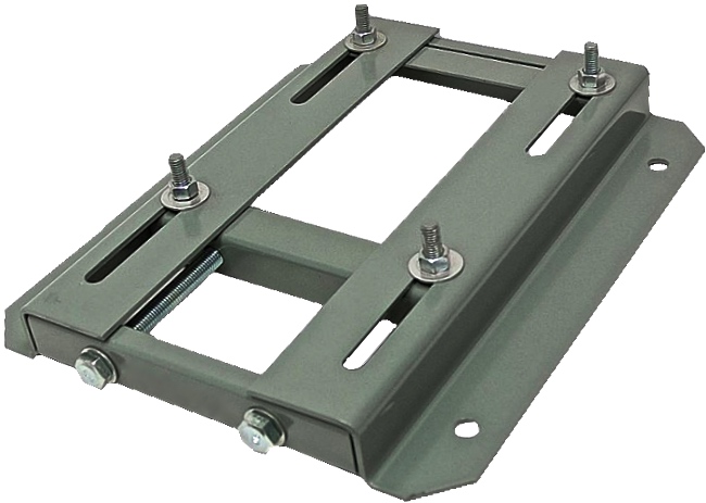
Are there specific safety considerations associated with motor base installation?
Motor base installation involves specific safety considerations that should be taken into account. Here’s a detailed explanation:
1. Electrical Safety: When installing a motor base, it is crucial to ensure proper electrical safety measures. This includes disconnecting power sources, following lockout/tagout procedures, and wearing appropriate personal protective equipment (PPE) such as insulated gloves and safety glasses. It is important to work with qualified personnel who are knowledgeable about electrical safety practices.
2. Lifting and Rigging Safety: Motor bases can be heavy, especially when combined with the weight of the motor. During installation, it is essential to use proper lifting and rigging techniques to prevent accidents or injuries. This may involve using appropriate lifting equipment, such as cranes or hoists, and ensuring that the motor base is securely attached to the lifting apparatus.
3. Structural Integrity: Motor bases need to be properly installed on a stable and structurally sound foundation. Ensure that the mounting surface can support the weight of the motor and base without any risk of collapse or instability. If necessary, consult with a structural engineer to assess the adequacy of the installation site and make any required modifications.
4. Secure Fastening: Properly and securely fasten the motor base to the mounting surface using appropriate bolts, screws, or anchors. Follow the manufacturer’s recommendations for torque specifications to ensure secure fastening without overloading or damaging the base. Loose or inadequate fastening can lead to instability and potential accidents.
5. Ergonomics: Consider ergonomic factors during motor base installation to prevent strain or injury to personnel. Use proper lifting techniques, provide adequate lifting aids or equipment, and ensure that the work area is free from clutter or obstacles. This helps reduce the risk of musculoskeletal injuries during the installation process.
6. Environmental Hazards: Evaluate the installation site for any potential environmental hazards that could affect safety. This includes identifying and mitigating risks such as slippery surfaces, obstructions, or the presence of chemicals or hazardous materials. Take appropriate precautions to ensure a safe working environment for the installation personnel.
7. Manufacturer Guidelines: Follow the manufacturer’s guidelines and instructions for motor base installation. These guidelines often include specific safety considerations and precautions that are relevant to the particular motor base model. Adhering to the manufacturer’s recommendations helps ensure safe and proper installation.
8. Inspections and Testing: After the motor base installation, conduct thorough inspections and testing to verify the integrity of the installation and ensure proper functionality. This includes checking for any loose connections, verifying proper alignment, and performing electrical tests as required. Regular inspections and testing also play a crucial role in ongoing maintenance and safety of the motor base.
It is important to note that the specific safety considerations may vary depending on factors such as the size and type of motor, the installation site, and applicable regulations. It is recommended to consult with experts in motor base installation and adhere to relevant safety standards and guidelines to ensure a safe and compliant installation process.
Can motor bases be used with both AC and DC electric motors?
Yes, motor bases can generally be used with both AC (alternating current) and DC (direct current) electric motors. Here’s a detailed explanation:
1. Universal Compatibility: Motor bases are typically designed to accommodate a wide range of motor types and sizes. They are engineered to provide a universal mounting interface that can support various motor configurations, including both AC and DC motors. This allows for flexibility and ease of installation regardless of the motor type.
2. Standardized Mounting Patterns: Motor bases often adhere to standardized mounting patterns, such as those defined by organizations like the National Electrical Manufacturers Association (NEMA) or the International Electrotechnical Commission (IEC). These standards specify the dimensions and hole patterns for motor mounting, ensuring compatibility with different motor types, including AC and DC motors.
3. Adjustability: Many motor bases feature adjustable mounting slots or bolt-hole patterns. This adjustability allows for fine-tuning the motor’s position and alignment during installation, regardless of whether it’s an AC or DC motor. Adjustability is especially important for achieving optimal alignment, which is crucial for motor performance and efficiency.
4. Mechanical Stability and Support: Motor bases provide mechanical stability and support to electric motors, regardless of their power source. They help secure the motor in place and prevent excessive vibration, ensuring reliable and efficient operation. The structural integrity and load-bearing capacity of motor bases are designed to handle the requirements of both AC and DC motors.
5. Application-Specific Considerations: While motor bases can generally be used with both AC and DC motors, it’s important to consider specific application requirements. AC and DC motors may have different operational characteristics, such as starting current, torque characteristics, or speed control methods. These differences may influence the selection of a motor base, particularly if the application demands specialized features or adjustments to accommodate the specific motor type.
When selecting a motor base for use with AC or DC motors, it’s advisable to consult the motor manufacturer’s recommendations and specifications. Additionally, consider any application-specific factors that may influence the choice of motor base, such as environmental conditions, load requirements, or vibration considerations.
By ensuring compatibility and proper installation, motor bases can effectively support and enhance the performance of both AC and DC electric motors across a wide range of applications.
What role does a motor base play in reducing vibration and noise from motors?
A motor base plays a crucial role in reducing vibration and noise generated by motors. Here’s a detailed explanation:
Electric motors can produce significant vibrations and noise during operation, which can have negative effects on equipment, structures, and human comfort. Motor bases are designed to minimize these vibrations and noise by performing the following roles:
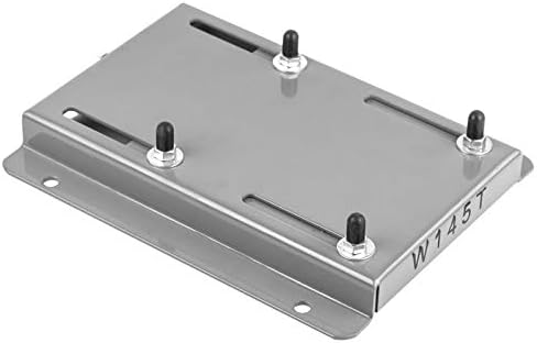
1. Vibration Dampening: Motor bases are constructed using materials and designs that help dampen the vibrations produced by motors. Materials with good vibration-dampening properties, such as steel or cast iron, are commonly used in motor bases. These materials absorb and dissipate vibrations, preventing them from propagating to the supporting structure. By reducing vibrations, motor bases help minimize the transmission of vibrations to surrounding equipment, which can prevent damage, improve performance, and extend the lifespan of connected machinery.
2. Isolation: Some motor bases incorporate isolation features to further reduce vibration transmission. These bases may include elastomeric mounts, springs, or other damping elements that isolate the motor from the mounting surface. These isolating elements absorb and dissipate vibrations, providing an additional layer of protection against vibration transmission. Isolation helps prevent vibrations from being transferred to the supporting structure, reducing the potential for structural damage and minimizing noise generation.
3. Stability and Alignment: Proper alignment and stability of the motor are essential for reducing vibrations. Motor bases provide a secure and stable mounting platform that ensures the motor remains properly aligned during operation. Proper alignment helps reduce vibrations caused by misalignment, unbalanced loads, or belt tension issues. By maintaining stability and alignment, motor bases contribute to smoother motor operation, minimizing vibrations and associated noise.
4. Noise Absorption: In addition to reducing vibrations, motor bases can also help absorb and dampen noise generated by motors. The materials and construction of the base can contribute to noise reduction. For example, motor bases made of sound-absorbing materials or incorporating noise-reducing designs can help mitigate the noise generated by the motor, creating a quieter working environment.
By addressing vibration and noise issues, motor bases contribute to improved equipment performance, reduced maintenance needs, enhanced operator comfort, and increased workplace safety. However, it’s important to note that the effectiveness of a motor base in reducing vibration and noise depends on factors such as the motor size, operating conditions, mounting configuration, and the specific design features of the base.
In summary, motor bases play a vital role in reducing vibration and noise from motors. They dampen vibrations, isolate the motor, provide stability and alignment, and can contribute to noise absorption. By minimizing vibrations and noise, motor bases help protect equipment, structures, and human well-being, ensuring smoother and quieter motor operation.


editor by CX 2024-05-10
Leave a Reply